F130
Digital indicator for OMRON SYSMAC CJ1/CJ2/NJ


Product outline
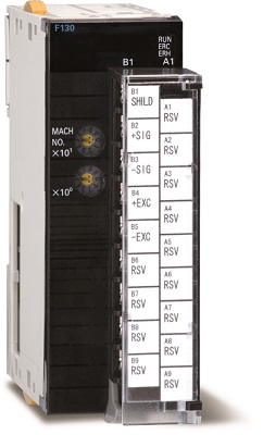
F130 is a loadcell interface that allows direct plug-in to OMRON’s general-purpose PLC SYSMAC CJ1/CJ2/NJ for strain gauge type sensors. Sensor output is quickly loaded as a digital value, and directly output to the CPU. Waste in production line is thoroughly eliminated to realize substantial cost reductions and high added value by reducing measurement system development time and improving maintenance management, modification and serviceability.
About the connection propriety of NJ series
CPU unit (NJ301/NJ501): ver.1.06 or later connectable
Sysmac Studio: ver.1.07 or later connectable
Specifications
Analog section|Display section|Terminal block|Setting section|Area (DM/relay)|Hold section|General performance|Attachments
| Analog section | |
| Excitation voltage | DC10V±5%, Output current: within 30mA (single 350Ω sensor) DC2.5V±5%, Output current: within 30mA (single 120Ω sensor or four 350Ω sensors in parallel) |
|---|---|
| Signal input range | -3.0 to +3.0mV/V |
| Accuracy | Non-linearity: within 0.02%/FS ±1digit (at 3.0mV/V input) Zero drift: within 0.5μV/℃ RTI Gain drift: Within 25ppm/℃ |
| A/D converter | ・ Speed: 3000 times/sec. ・ Resolution: 24bit (binary), 1/10000 to 1.0mV/V input |
| Analog filter | Low pass filter (-6dB/oct.) Selectable at 30, 100, 300, 1000Hz |
| Display section | |
| Status LED | RUN (Green): Turns on when normal operation ERC (Red): Turns on when an alarm occurs or blinks when an error occurs in the F130 ERH (Red): Turns on when an alarm occurs in data exchange with the CPU unit |
|---|---|
| Terminal block | |
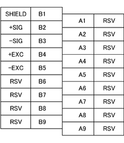
| Detachable terminal block (M3 screw) * RSV: Never connect anything to the RSV terminals. |
 |
|---|---|
| Setting section | |
| Unit No. rotary switch | High performance I/O unit No. setting: 0 to 95 unit |
|---|---|
| Setting method | Made from the CPU unit via the data memory(DM) area defined for the F130. |
| Set value Storage | Calibration value: Stored in NOV RAM (non-volatile RAM) Set value: Measurement stats with the set values (DM area) written from the CPU unit after power-on. (Not stored on the F130 side) |
| DM (data memory) area | |
| Setting item | Excitation voltage, Minimum scale division, Analog filter, Digital filter count, Digital offset, Sensor rated output value, Sensor rated capacity value |
|---|---|
| Relay area | |
| F130→CPU | Measurement value (-32768 to 32767), Data update counter, Peak hold value (In calibration mode: sensor rated output value), Bottom hold value (In calibration mode: sensor rated capacity value), Average value (In calibration mode: sensor output value at the Zero calibration point), Average count (In calibration mode: calibration error number), Measurement value overflow, A/D input range over |
|---|---|
| CPU→F130 | Mode selection (Normal operation mode-Calibration mode ), Equivalent input calibration, Actual load calibration, Zero calibration, Survival confirmation, Hold value clear, Hold (section specification), Digital zero |
| Hold section | |
| Peak, Valley, Average (Simultaneous hold) | |
| General performance | |
| Consumption current | DC5V Approx. 0.46A (At excitation voltage DC10V, single 350Ω sensor) |
|---|---|
| Operating conditions | Temperature: Operation temperature; 0℃ to +55℃] Accuracy compensation applicable; temperature 0℃ to +40℃ Storage temperature; -20℃ to +75℃ Humidity: 90%RH or lower (non-condensing) |
| Dimensions | 31(W)×90(H)×65(D) mm (protrusion excluded) |
| Weight | Approx. 160g |
| CE marking certification | EMC Directives: EN61131-2(CLASS A) |
| Attachments | |
| Operation manual | 1 |
|---|---|
Download
|
Product catalogue(PDF)
|
F130 Product catalogue Dowmload | |
|---|---|---|
|
Operation manual(PDF)
|
|
|
|
External dimention
|
DXF
(ZIP) |
|
|
PDF
|
||
|
Support tools
|
||
|
Software
|
||
- User registration is required to download operation manuals, external dimentions, support tools and software .
- Acrobat Reader software from Adobe Systems is required to view PDF files.