F395
LCD touch panel display digital indicator


Product outline
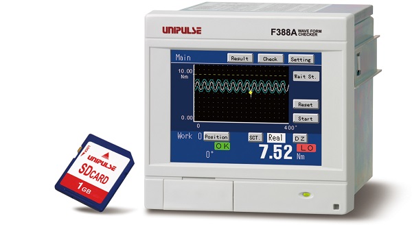
F395 is a dynamic force processor integrated with a strain gauge sensor that can display physical quantities such as pressure, load and torque in waveforms. It is able to visually capture in waveforms the fluctuations in physical quantities which are difficult to capture by only numerical values. With a maximum 4000 times per second for high-speed processing, it is also ideal for narrow value fluctuations and comes equipped with a HI/LO limit comparison function, various hold functions and judgment function. F395 can be used in a wide-range of applications such as in control systems used in production control, automatic devices or testers.
Specification
Sensor input|Strain gauge input|Voltage input|Current input|Pulse input|Display section|Setting section|Measurement functions|I/O section|General performance|Attachments
| Sensor input | |
| Number of sensor inputs | 2 inputs (Std: CH1=strain gauge input; CH2=voltage input)(As an option, CH1 can be switched to voltage/ current input and CH2 can be switched to strain gauge/ current input); CH1: Fixed Y-axis; CH2: settable X-Y axes (W/ pulse option: fixed Y-axis at analog input [strain gauge, current, voltage]) |
|---|---|
| Strain gauge input | |
| Excitation voltage | 10V DC/ 2.5V interchangeable (according to setting) Output current: 120 mA or less (for 2 inputs total) 4-wire type (at 1 input: up to 4 units of 350Ω strain gauges may be parallel-connectable) |
|---|---|
| Signal input range | -3.0mV/V to +3.0mV/V |
| Zero/gain adjustment | Via digital processing |
| Equiv. input cal. range | +0.5mV/V to +3.0mV/V, -3.0mV/V to -0.5mV/V |
| Equiv. input cal. range error | Within 0.2% FS |
| Accuracy | Non-linearity: within 0.02%/FS ±1 digit (at 3.0mV/V input) Zero drift: within 0.5μV/°C RTI (input conversion value) Gain drift: within 0.01%/°C |
| Analog filter | Selectable from 10, 50, 200, 600 Hz Bessel low-pass filter (-12dB/oct.) |
| A/D converter | Speed: At 1 input – 4000 times/sec. (max) At 2 inputs – 2000 times/sec. (at max. speed, sensor 2-input measurements) Depending on input waveform, changeable to 100, 200, 500, 1000, 2000 times/sec. Resolution: 16bit (binary ) Approx. 1/30000 at 3.0mV/V |
| Voltage input | |
| Signal input range | -5V to +5V |
|---|---|
| Input impedance | 5kΩ or more |
| Zero/gain adjustment | Via digital processing |
| Equiv. input cal. range | +1V to +5V, -5V to -1V |
| Equiv. input cal. range error | Within 0.2% FS |
| Accuracy | Non-linearity: within 0.02%/FS ±1digit (at 5V input) Zero drift: within 50μV/°C RTI (input conversion value) Gain drift: within 0.05%/°C |
| Analog filter | Selectable from 10, 50, 200, 600 Hz Bessel low-pass filter (-12dB/oct.) |
| A/D converter | Speed: At 1 input – 4000 times/sec. (max) At 2 inputs – 2000 times/sec. (at max. speed, sensor 2-input measurements) Depending on input waveform, changeable to 100, 200, 500, 1000, 2000 times/sec. Resolution: Approx. 1/27000 at 5V |
| Current input | |
| Signal input range | -20 to +20mA |
|---|---|
| Input resistance | Approx. 100Ω |
| Zero/gain adjustment | Via digital processing |
| Equiv. input cal. range | +8mA to +20mA, -20mA to -8mA |
| Equiv. input cal. range error | within 0.2% FS |
| Accuracy | Non-linearity: within 0.02%/FS ±1digit (at 20mA input) Zero drift: within 2μA/°C RTI (input conversion value) Gain drift: within 0.05%/°C |
| Analog filter | Selectable from 10, 50, 200, 600 Hz Bessel low-pass filter (-12dB/oct.) |
| A/D converter | Speed: At 1 input – 4000 times/sec. (max) At 2 inputs – 2000 times/sec. (at max. speed, sensor 2-input measurements) Depending on input waveform, changeable to 100, 200, 500, 1000, 2000 times/sec. Resolution: Approx. 1/26000 at 20mA |
| Pulse input (Optional) * If opted, analog input (loadcell/current/voltage) will exclusively be of Y-axis measurement. |
|
| Max. input frequency | 50kHz |
|---|---|
| Max. counting range | 0 to 65535 1/4, 1/16, 1/64 divider function can be added via setting before the counter. |
| External supply power | DC5V (150mA MAX) |
| Applicable sensor | Option-compatible sensor specifications: Output: Incremental type 2-phase output (A, B signal) – also ideal for 1 phase output (A phase input is available. All pulses are counted as plus direction) Output stage circuit specification: One of the following is set before shipment 1. Open collector (NPN type, Vceo=10V or more, Ice=30mA or more) 2. Line driver (Based on RS-422) |
| Display section | |
| Display | TFT color LCD |
|---|---|
| Display area | 116.8(W)×88.0(H) mm |
| Dot structure | 320×240 dot |
| Measured value display |
Y-axis: 4 digits (-9999 to +9999), X-axis: 5 digits (-9999 to +19999) |
| Display count | 0.1 to 9.9 sec./ display update, selectable |
| Setting section | |
| Setting method | Via touch panel screen |
|---|---|
| Setting value storage | Default: NOV RAM (nonvolatile RAM) Other setting values: C-MOS RAM with backup of a lithium battery |
| Measurement functions | |
| Multi-hold function | 32ch; 20 types of hold modes Sample, Peak, Valley, P-P (Peak to Peak), Period Specified (Peak, Valley, P-P), Time Specified (Peak, Valley, P-P), Time Specified Auto (Peak, Valley, P-P), Relative Minimum Value, Relative Maximum Value, Inflection Point (A, B, C, D), External Pulse |
|---|---|
| Waveform comparison mode and waveform & displacement mode | 16ch; stores up to 2048 data patterns and judges if the data are within the pattern range (in/out of range comparison) |
| Hysteresis/ Hysteresis 2 mode | Displacement input is set as X-axis and forward/ return waveform is done for each hold. |
| Other functions | Interchangeable for digital zero/ Digital filter/ Calibration values and set values LOCK/ External signal interlock, hold mode selection (multi-holding: 32ch memory; waveform comparison and waveform & displacement: 16ch memory (pattern)/ Displacement sensor input continuous judgment/ NG waveform 4 times storing for playback (up to 2 times for Hysteresis mode) |
Option
| I/O section * Interface option: Up to 3 options allowable; serial communication interface (ODN, CCL) is only one. |
|
| Input signal (24 points) | ON when a short circuit occurs at COM terminal by contact (relay, switch) or non-contact (transistor, open collector). |
|---|---|
| Output signal (16 points) | Transistor’s open collector output (Emitter=COM terminal); Output is ON when transistor is ON. |
| Analog output | Approx. 2V for 1mV/V loadcell input (Load resistance 5kΩ or more); Approx. 5.6V for 5V voltage input; Approx. 5.2V for 20mA current input |
| SIF | 2-wire type serial interface (standard); Interface to link with Unipulse printer or external display |
| 232 | RS-232C communication interface (standard); Read/write setting values via commands from host computer |
| PUI | Pulse input interface (Optional); Interface for link with open collector type/ line driver output type pulse transmitter |
| ODN | DeviceNet interface (Optional); Interface to link F395 to DeviceNet such as OMRON CompoBus/D |
| CCL | CC-Link interface (Optional); Interface to link F395 to CC-Link such as Mitsubishi sequencer to set up a network |
| General performance | |
| Power supply voltage | AC100 to 240V (+10% -15%); 50/60Hz |
|---|---|
| Power consumption | 25W (50VA) max (at constant 240V AC) |
| Inrush current |
20A, 5msec: 100V AC max. load condition (ordinary temperature, at cold-start) 40A, 5msec: 200V AC max. load condition (ordinary temperature, at cold-start) |
| Operating conditions | Temperature: Working temperature range -10 to +40°C; Storage temperature range -20 to +60°C Humidity: 85% RH or less (non-condensing) |
| Dimensions | 174(W)×135(H)×156(D) mm (protruding parts not included) |
| Weight | Approx. 2.3kg |
| CE marking certification | EMC Directives EN61326-1 Lower Voltage Directives EN61010-1 (CE marking has not yet acquired for CCL options) |
| Attachments | |
| AC input cord (Nominal rating 125V) 2m | 1 |
|---|---|
| 3P-2P AC input cord conversion plug | 1 |
| Mini-driver for terminal block connection | 1 |
| 57 series 50P connector for external I/O cord | 1 |
| Ferrite core | 4 |
| Pulse input connector (when optional pulse input is installed) | 1 |
| DeviceNet connector (when optional DeviceNet is installed) | 1 |
| CC-Link connector (when optional CC-Link is installed) | 1 |
| Operation manual | 1 |
Option
| Model | |
| VI1 | CH1 voltage input |
|---|---|
| CI1 | CH1 current input |
| LI2 | CH2 loadcell input |
| CI2 | CH2 voltage input |
| PUI | Pulse input |
| ODN | DeviceNet interface |
| CCL | CC-Link interface |
Optional accessories
| Model | |
| CAAC3P-P2 | AC Supply cord 2m |
|---|---|
| CAAC3P-CEE7/7-P1.5 | AC Supply cord (Voltage resistance: 250V) 1.5m |
| CN3P-2P | 3P-2P converter plug for AC input cord |
| CN20 | Pulse input connector |
| CN22 | 57 series 50p connector for external input/output |
| CN34 | D-Sub9p connector for RS-232C |
| CN71 | CC-Link connector |
| CND01 | DeviceNet connector |
| CVR57 | Dust cover set |
| TSU02 | Lightning surge unit |
Download
|
Product catalogue(PDF)
|
F395 Product catalogue Dowmload | |
|---|---|---|
|
Operation manual(PDF)
|
|
|
|
External dimention
|
DXF
(ZIP) |
|
|
PDF
|
||
|
Support tools
|
||
|
Software
|
||
- User registration is required to download operation manuals, external dimentions, support tools and software.
- Acrobat Reader software from Adobe Systems is required to view PDF files.